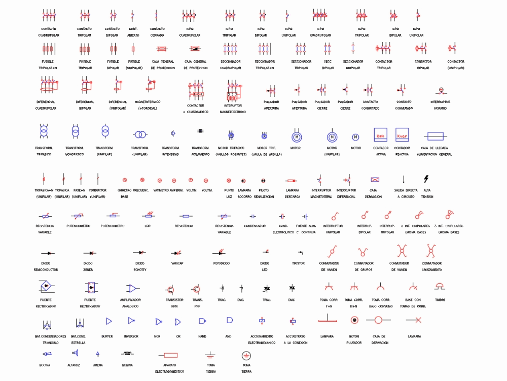
What are the different electrical symbols? How to draw electrical symbols? What is the basic electrical wiring? Wiring diagrams use special symbols to represent the switches, light, outlet and electrical equipments.
Here is a standard wiring symbol legend showing a detailed documentation of common symbols that are used in wiring diagrams , home wiring plans, and electrical wiring blueprints. The standard electrical symbols are smart, industrial standard and vector-based for electrical schematic diagrams. For example, a switch will be a break in the line with a line at an angle to the wire , much like a light switch you can flip on and off.
A resistor will be represented with a series of squiggles symbolizing the restriction of current flow. An antenna is a straight line with three small lines branching off at its en much like a real antenna. If you want to make sense of electric symbols on your blueprints then you’ve come to the right place.

The placement of the outlets for all the electrical items in your home can have a significant impact on the design of your home. Electric Symbols on Blueprints. These sy mbols are largely standardized internationally today, but may vary from country to country, or engineering. Variety of electrical wiring schematic symbols.
A wiring diagram is a streamlined conventional photographic depiction of an electrical circuit. It reveals the components of the circuit as simplified forms, and also the power as well as signal links between the devices. The hot wire carries power from the panel to the device you are wiring. Red wire blue, or other colors also indicate hot wires. Important Note: When wires or cables such as Romex are used with switching applications and as Switch Legs, the function of a colored wire may be different from what is noted here.

A must have for every electrical contractor. Bookstore JavaScript seems to be disabled in your browser. Give students a standard photocopy of a floor plan (see the end of this Activity Plan) that includes a kitchen and have them draw one or two 12-device circuits using electrical symbols and paths for circuits as shown in the floor plan drawing (Figure 5).
The most commonly used electrical blueprint symbols including plug outlets, switches, lights and other special symbols such as door bells and smoke detectors are shown in the figure below. Note: Explanations for common household electrical items such as three-way switches and switched duplex plug outlets are below the figure. INSCRIPTION ON CIRCUIT AND CABLES SHALL BE WRITTEN ALONG THE SYMBOLS AND SHALL BE READ FROM LEFT TO RIGHT OR FROM BOTTOM TO TOP. CONTACTS OF ELECTRICAL OPERATED DEVICES SHALL BE SHOWN IN THE DE- ENERGIZED POSITION.
Enter ZIP For Quotes in Seconds. No Obligation to Start, Always Free to Use. It uses simplified conventional symbols to visually represent electrical circuits and shows how components are connected with lines.
For example, a few basic symbols common to electrical schematics are shown as: (1) Switch, (2) Battery, (3) Resistor and (4) Ground. These electrical schematic symbols will help you to identify parts when working with an electrical schematic. There are different country-specific standards, IEC (British), ANSI, and AS (Australian Standard), that define the symbols used in circuit diagrams across the world. Common types of electrical symbols.
However, today most of the symbols are internationally standardized. Continuously Adjustable Resistor. Normally open foot switch. Timer off delay, normally open. Shielded transformer with magnetic core.
Thermally operated relay with.
No comments:
Post a Comment
Note: only a member of this blog may post a comment.